Webhdx’s WiiMini-SDRST Mod kit
Introduction
Adding a reset switch and an SD card slot to the Wii mini are relatively simple mods, however they might prove inelegant. This mod kit made by Webhdx aims to solve that by providing a clean, easy to install solution. It is designed to fit flush inside the dvd tray and accepts a microSD card.
Parts/Tools Required
- Webhdx’s WiiMini-SDRST Mod kit, which you can purchase on Tindie
- A good quality soldering iron
- A multimeter with at least continuity mode for testing
- 2mm and 4mm drill bits
- Kraft knife or similar
- small file
- microSD card (for putting in the microSD card slot)
Installation - debug pin pcb
- Take the quick solder PCB (the one with the lots of holes) and align it with the test points of section C on the bottom side of the Wii mini motherboard, as shown below:
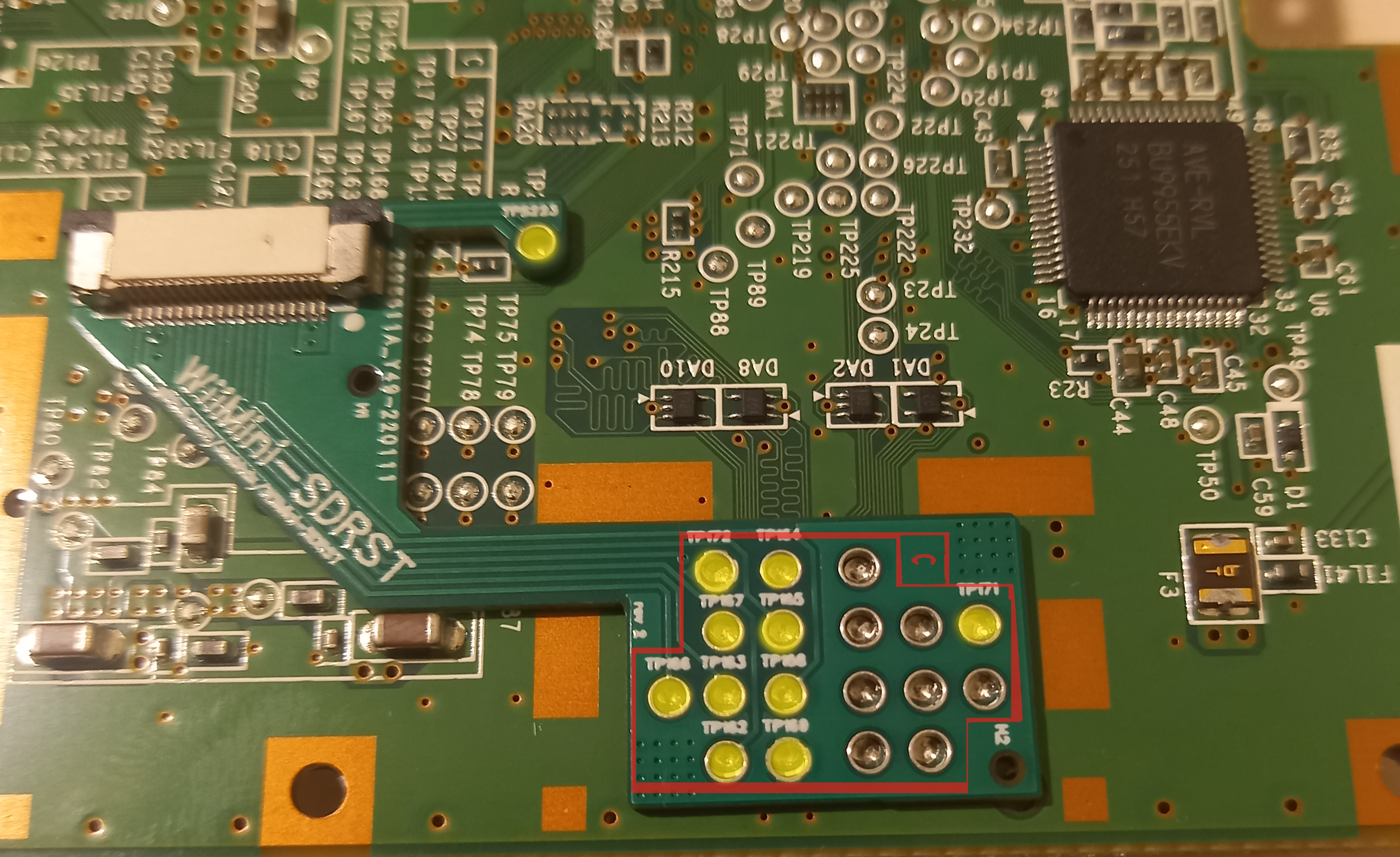
-
Solder the pins that have test point numbers on them (marked yellow in the image above) to the corresponding test points on the motherboard. The other pins can be left unconnected.
If your Wii mini happens to have its test points pre-tinned with leaded solder, it is highly recommended you wick off not only the pads you are going to solder to, but also any pads that happen to be under the qsb board, which could induce strain to it when soldered and break the solder joints over time.
- Use a multimeter to check if the pads have shorted underneath the qsb board. If they have, you will need to remove the solder from the pads and re-solder them, making sure to not use too much solder.
-
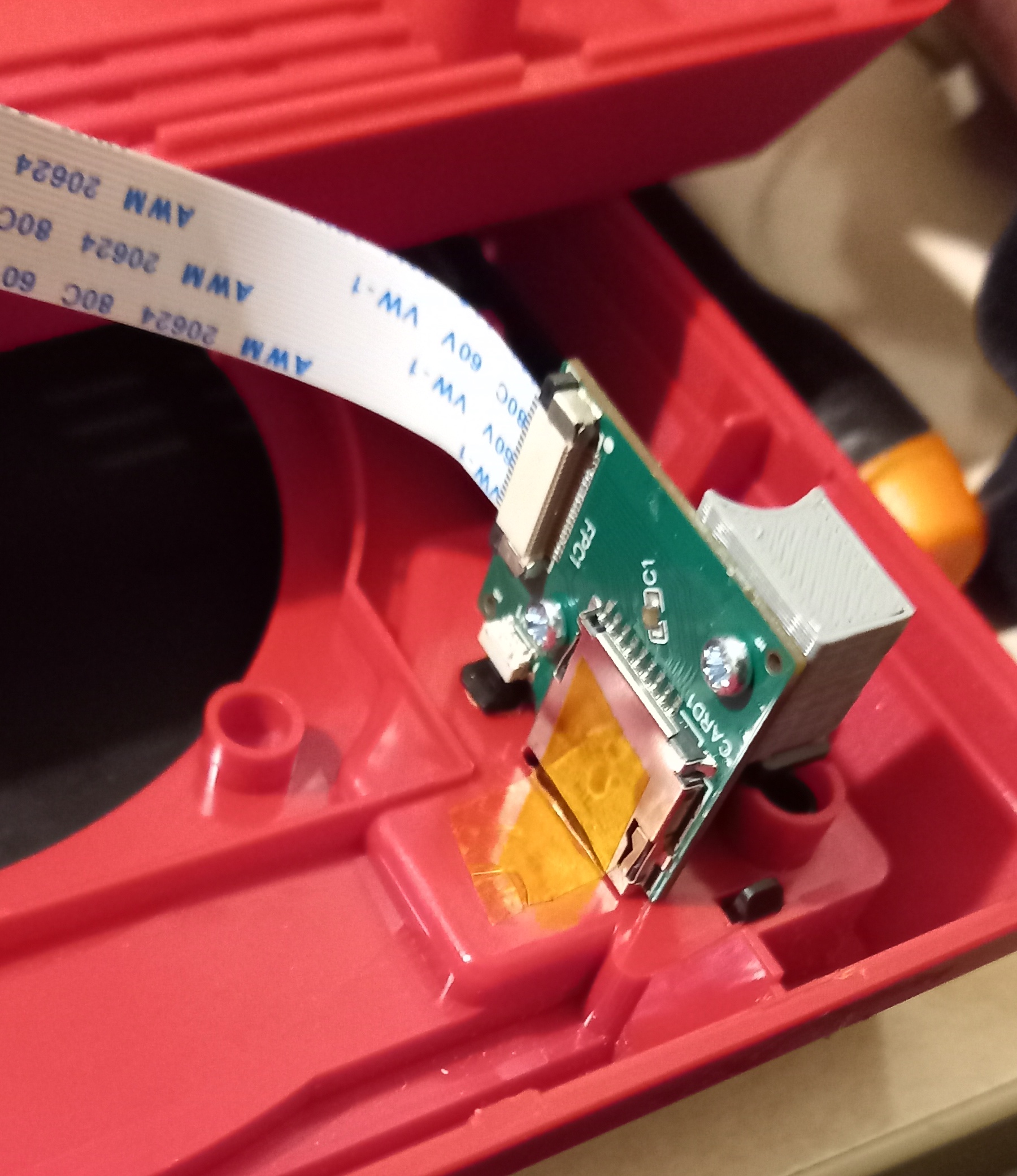
Take the ffc cable included in the kit, undo the zif latch by pulling the latch outwards, then insert the cable into the zif socket with the blue part facing down. Make sure the cable is inserted about 2/3rds of the way in, then re-latch the zif socket.
You should slowly walk the latch inwards by pushing the sides alternatingly until it fully seats into place. Do not push too hard or you might break the latch. If it isn’t moving, try removing and reseating the cable or making sure it is inserted fully.
-
Make a 90 degree bend in the cable towards the front (flat) side of the board, at about the height of where the unpopulated wifi slot is on the other side, making sure you don’t go over any screw holes, or you will screw through the cable during reassembly.
Do not fold the cable completely flat on itself like you would on a piece of paper, as it may crack the cable internally.
Your board should now look something like this:
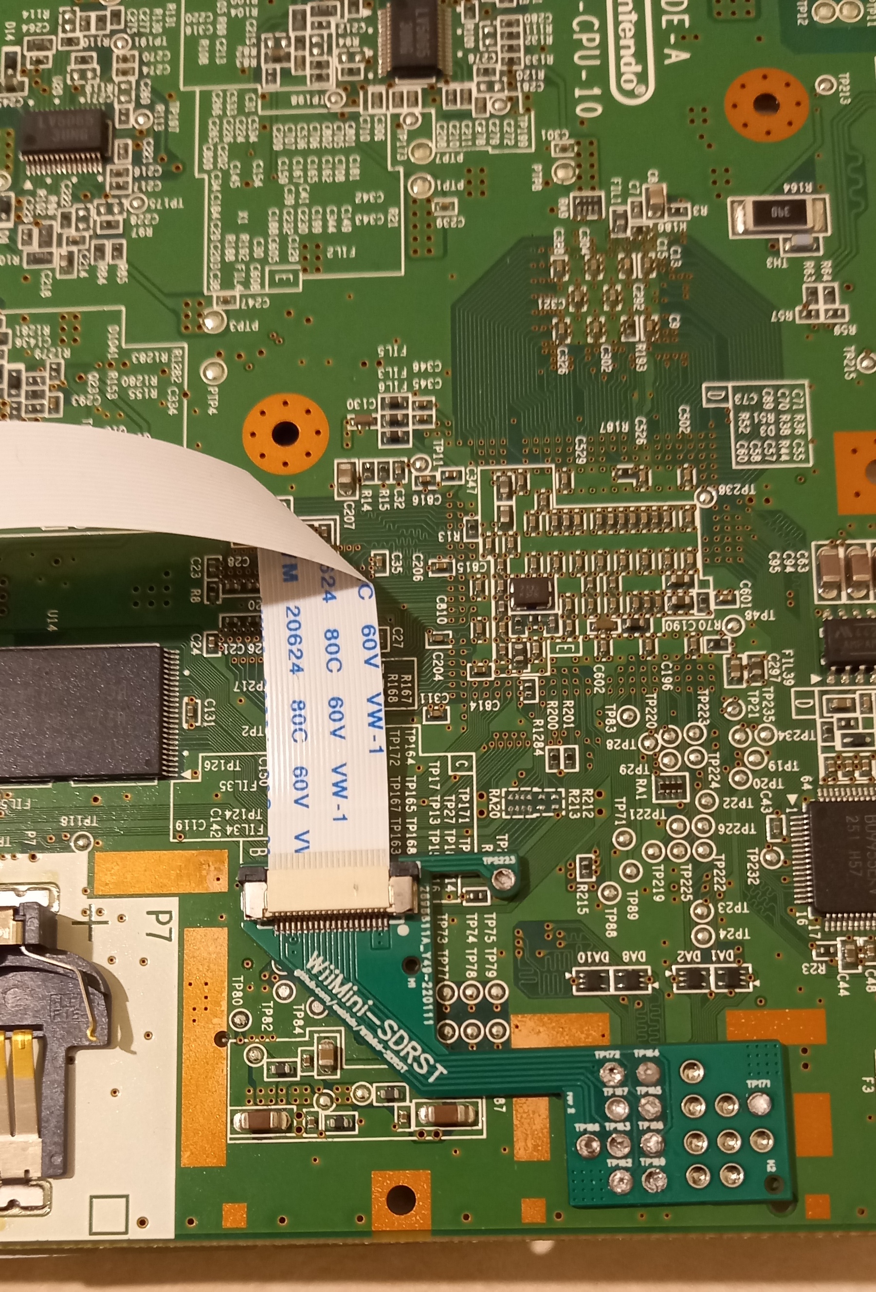
You may now set the motherboard aside.
Installation - case mod
You will need to drill a few holes on the top shell of the Wii mini for the microSD and reset button to peek through. The kit comes with two 3d printed drill guides to help you with the process.
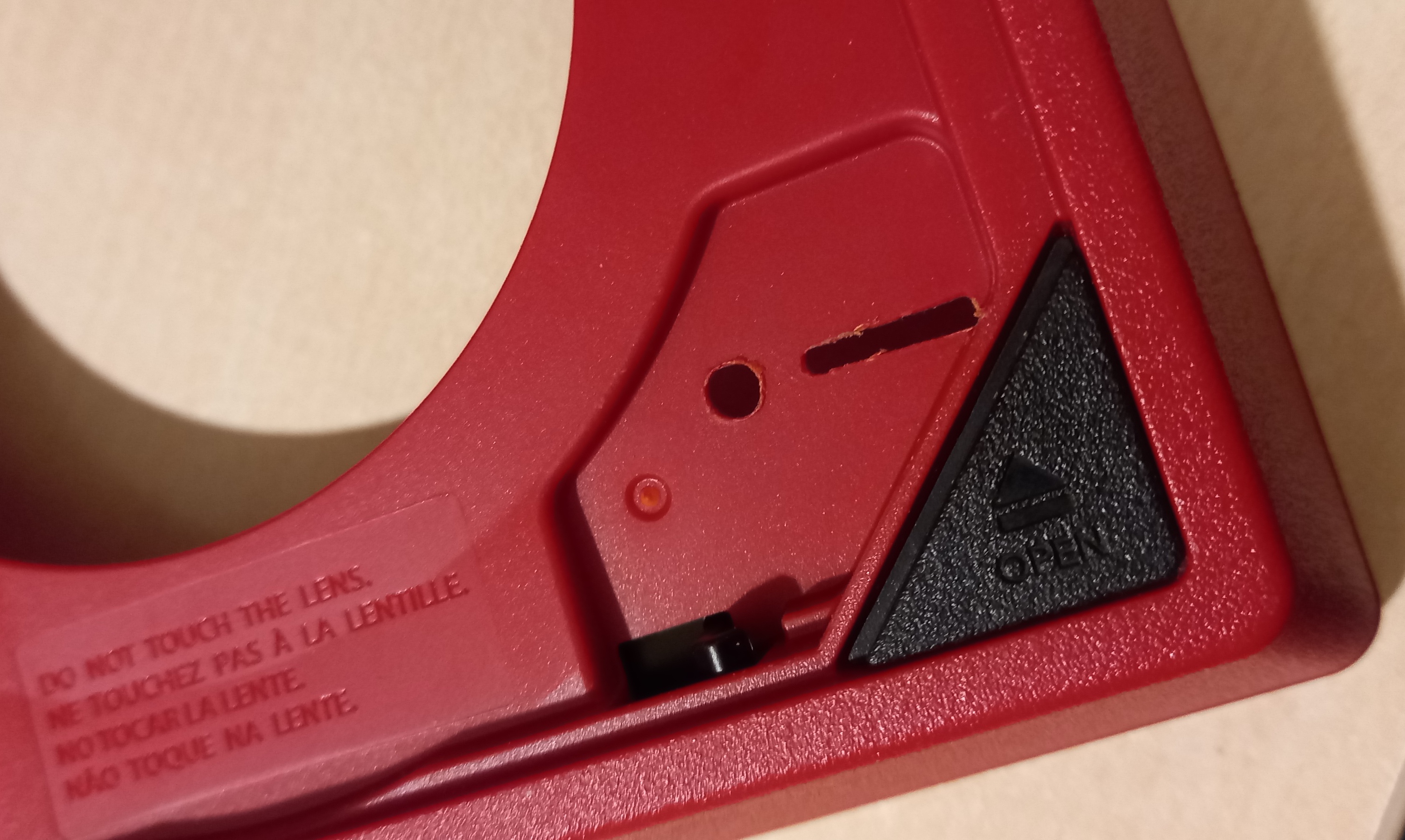
- Take the drill guide with 4 small and one big hole and place it on the screw post next to the disc eject button of the shell, as shown below:
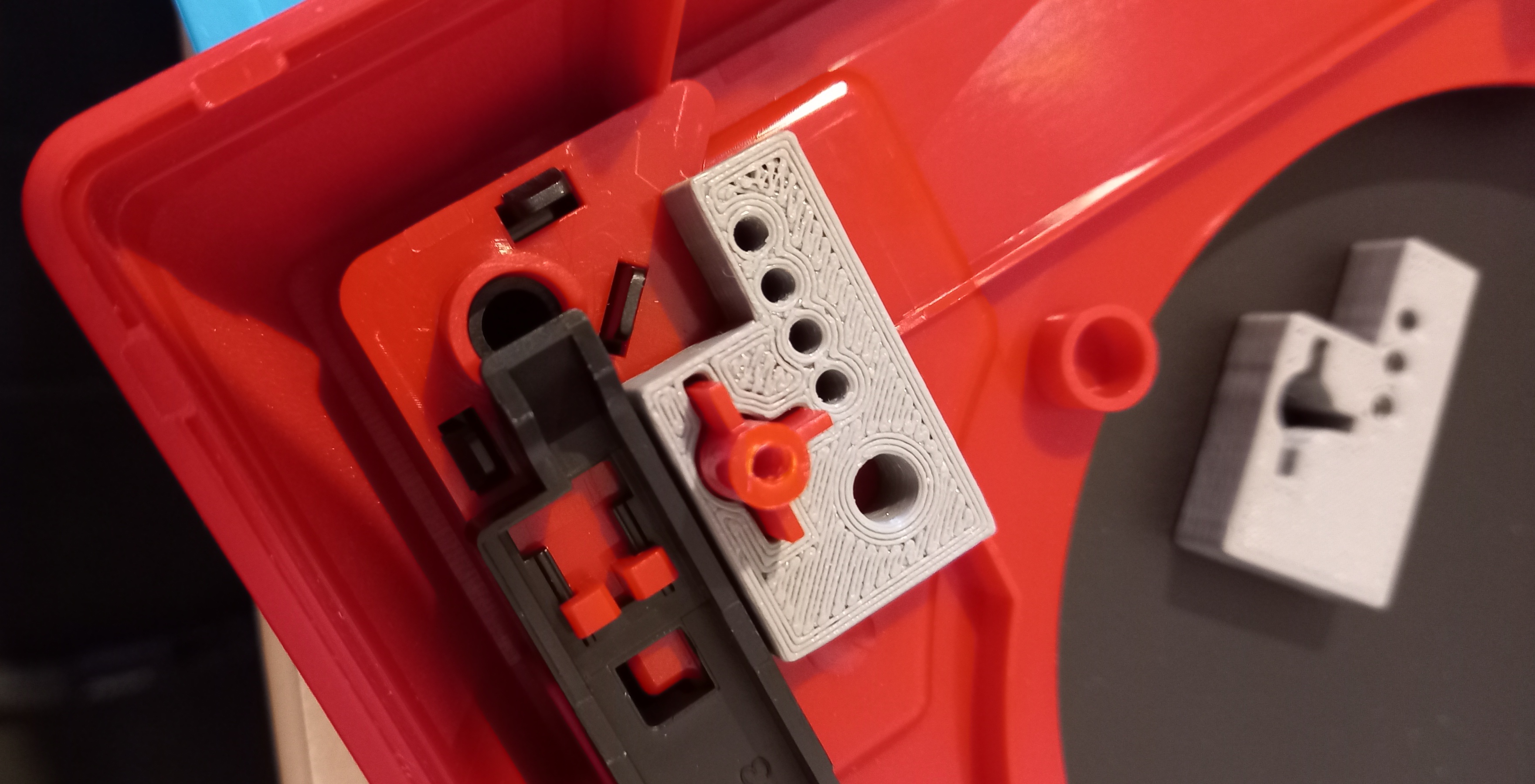
-
Using a 4mm drill bit, drill through the big hole for the reset switch.
Make sure you only drill through the red shell and not the black disc cover. If it helps, you may keep the cover open or remove it altogether.
- Using a 2mm drill bit, drill through the small holes for the microSD card slot.
- Repeat for the other drill guide’s 3 2mm holes.
You should end up with something similar to this:
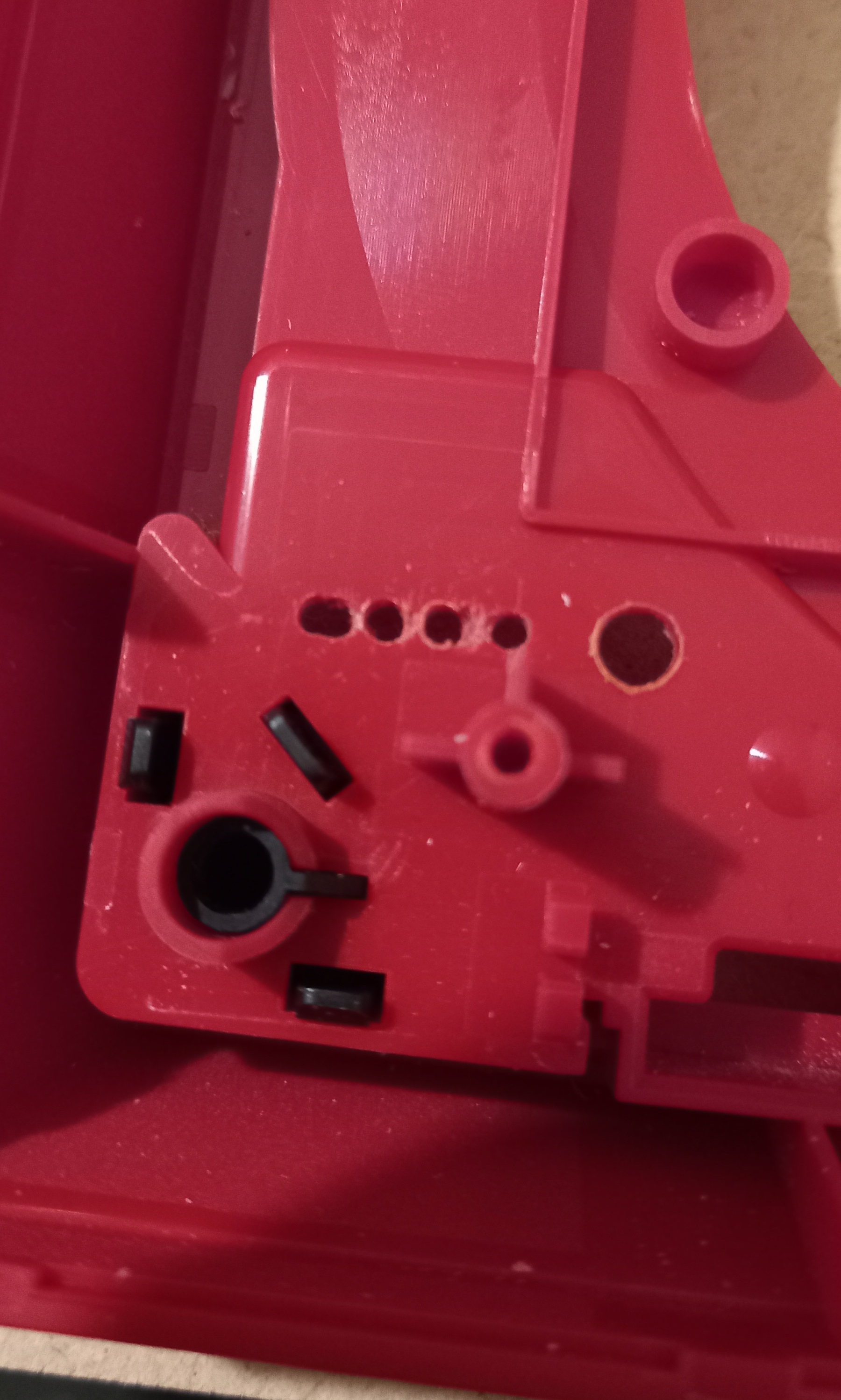
- Take your craft knife or other sharp tool and break apart the small dividers between the drill holes, then use a file to create a wide opening for the microSD card slot. Use a brush, compressed air or other means to remove any plastic shavings.
After all the post-processing is done, you should end up with something similar to this:
It is now a good time to place the little 3d printed reset button in the big hole you drilled and test if it fits. If it doesn’t, you may need to file the hole a bit more. You should also check that the sd card slit is wide enough for the microSD card to fit through.
Installation - Final assembly
Now that both sides of the mod are ready, it’s time to put everything together.
- Place the motherboard back inside the case and assemble the rest of the case as you would normally.
- attach the ffc cable to the sd card slot pcb, making sure the blue part is facing down.
- Insert the 3d printed button cap in the big hole of the top half of the case then insert the sdrst pcb on the screw post next to the disc eject button. You can use a little bit of sticky tape to hold the board in place.
- Close up the case and screw it back together.
Post-Install
Congratulations! The sdrst mod should now be installed. However, in order to use it, you will need to install the original Wii System Menu, if you haven’t already.
If you do not have a WiFi card already installed, proceed to installing the System Menu (no WiFi card)
If you already have a WiFi card installed, you should have already re-installed the System Menu.
We’d love to see your completed mod, feel free to join us on our Discord and post a picture in #pimping-general
Return to Pick-a-Pimp | Continue to site navigation
We have other tutorials that you might like.