miniRGBii Component Mod
Introduction
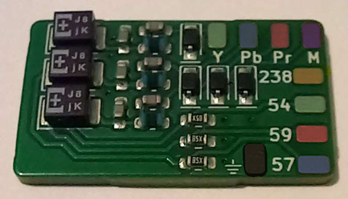
One feature that really sets the Wii mini apart from its older brother, is the lack of clear, 480p Component video. Instead, the console is limited to only interlaced outputs over Composite, resulting in a relatively terrible image. However, members of the Wii mini hacking community have managed to create a board that allows you to use the Wii Component cable and get full progressive scan.
Parts/Tools Required
- Job and Devnol’s miniRGBii board, which you can purchase on Tindie or get the Open Source KiCAD files from our GitHub to manufacture it yourself.
- A Wii AV Component cable. Though Nintendo no longer sells these, you can get 3rd party options in varying quality and price ranges.
- Very thin wrapping or enameled magnet wire (≤30awg)
- A quality soldering iron with a fine tip
- Double-sided and/or heat-resistant (Kapton) tape for tacking down the board and wires (optional but recommended)
Instructions
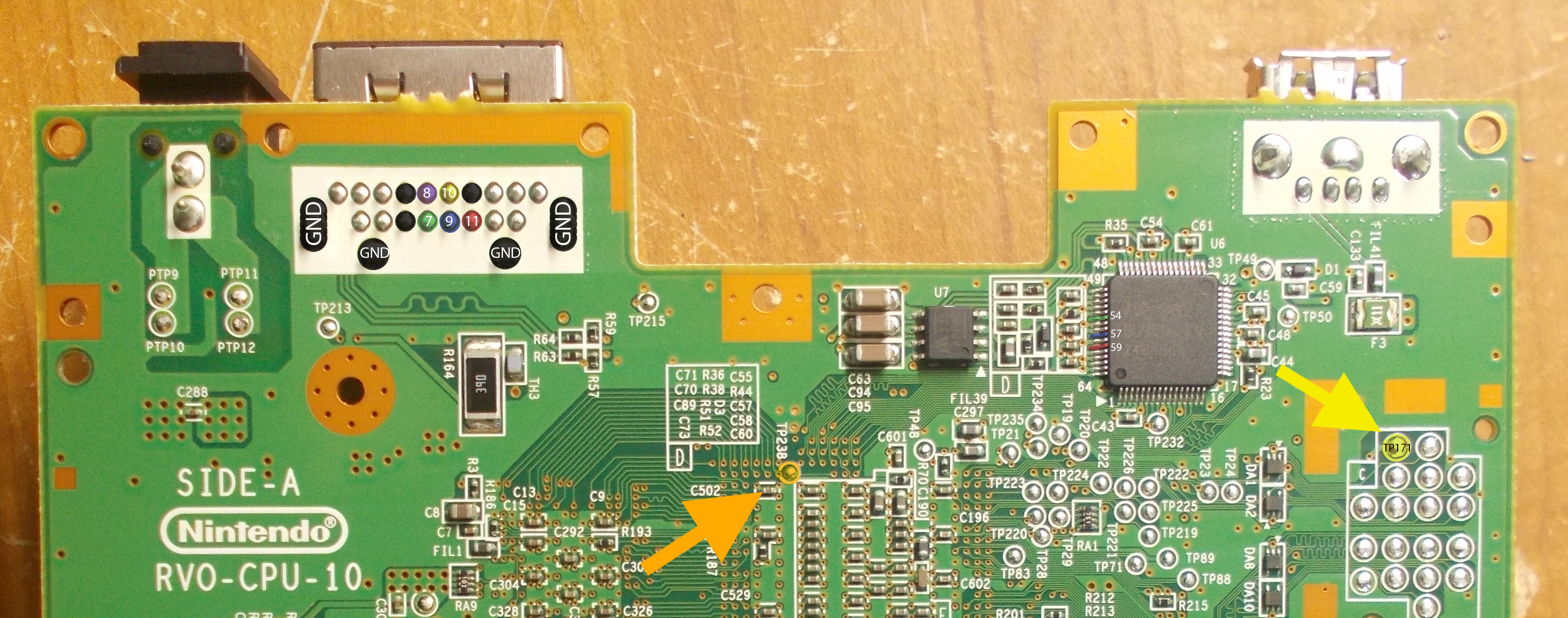
- Find a good placement for the minirgbii board and secure it with double-sided or kapton tape. A good position is ideally close to the AV Multi Out connector, as well as the AVE-RVL chip.
-
Make the following connections from the miniRGBii board to the respective points on the Wii mini motherboard, using as short wires as possible to minimize interference:

 (Right Click an image > Open in New Tab (or pinch on a touchscreen/trackpad) to zoom)
- GND sink (⏚) to any ground pad on the board (coloured black)
- Component green Pad labeled
Yto AV connector pin 7 (coloured green) - Component blue Pad labeled
Pbto AV connector pin 9 (coloured blue) - Component red Pad labeled
Prto AV connector pin 11 (coloured red) - Mode pin Pad labeled
Mto AV connector pin 8 (coloured purple) - AVE green Pad labeled
54to AVE chip pin 54 (coloured green)^ - AVE blue Pad labeled
57to AVE chip pin 57 (coloured blue)^ - AVE red Pad labeled
59to AVE chip pin 59 (coloured red)^ - Mode enable Pad labeled
238to board test pad TP238 (coloured orange) - You also need to directly supply 3.3v by connecting the AV connector’s pin 10 to TP171 on the motherboard (coloured yellow)
^: The AVE chip is located south-west of the USB port. Pin numbering starts from 1 on the bottom left side and continues counter-clockwise, as shown by the silkscreen on its corners.
- You may optionally tape down the wires with kapton tape to prevent them from moving and getting caught on things, which can in turn rip copper pads off the board.
Post-Install
Congratulations! You should now have component video wired up. However, in order to use it, you will need to install the original Wii System Menu, if you haven’t already.
If you do not have a WiFi card already installed, proceed to installing the System Menu (no WiFi card)
If you already have a WiFi card installed, you should have already re-installed the System Menu.
We’d love to see your completed mod, feel free to join us on our Discord and post a picture in #pimping-general
Return to Pick-a-Pimp | Continue to site navigation
We have other tutorials that you might like.